 English
 中文简体
 русский
 عربى


1.The circuit breaker provides safety protection, arc extinguishing, and interrupting functions, with defined electrical life and short-circuit withstand capability. 2.Multiple controller options are ...
See Details
Circuit Breaker Operating Time vs Tripping Time: What They Mean and Why They Matter
Content
- 1 Operating Time: The Mechanical Half of the Equation
- 2 Tripping Time: The Release Response
- 3 Total Clearing Time: Adding the Stages Together
- 4 Reading a Time-Current Trip Curve
- 5 What Happens Inside: Components That Set the Timing
- 6 Practical Checks for Buyers and Test Engineers
- 7 Frequently Asked Questions About Circuit Breaker Operating Time and Tripping Time
- 7.0.1 Q1: What is the difference between circuit breaker operating time and tripping time?
- 7.0.2 Q2: What is a typical circuit breaker trip time at short circuit?
- 7.0.3 Q3: What is the opening time of a circuit breaker?
- 7.0.4 Q4: What does the trip curve on an MCCB datasheet mean?
- 7.0.5 Q5: What factors affect circuit breaker tripping time?
- 7.0.6 Q6: How can I reduce circuit breaker trip time?
A maintenance engineer in a low-voltage switchgear shop picked up a routine test certificate for a 400 A moulded case circuit breaker and noticed two numbers that did not seem to agree: tripping time 18 ms, operating time 23 ms. Both figures are printed on the same document, yet they describe different stages of the same fault-clearing sequence. Put simply: tripping time is how quickly the release detects the overcurrent and commands the mechanism to open, while operating time is how quickly the mechanism then separates the contacts. Add arcing time, and you reach the total clearing time that protection coordination studies actually use.
This article explains both definitions, gives typical values from standards and field data, and identifies the components that control each interval.
Operating Time: The Mechanical Half of the Equation
Operating time, also called opening time or mechanical operating time, is measured from the moment the trip release is energized to the instant all poles reach contact separation. IEC 60947 uses this boundary for low-voltage equipment testing, and the same interval appears in ANSI timing reports and circuit breaker analyzer printouts. It is a purely mechanical quantity: latch friction, operating spring force, moving-contact mass, linkage clearances, and contact travel all contribute. Nothing about the release's detection speed is included here.
These mechanical variables explain why operating time differs by equipment class. EPRI's circuit breaker timing study, which summarized field tests for several medium- and high-voltage breaker families, reported opening times of 23 to 42 ms and closing times of 50 to 95 ms depending on the model and mechanism. Low-voltage moulded case breakers are usually faster because their contacts are lighter and travel is shorter.
Tripping Time: The Release Response
Tripping time is the detection stage. It begins when a fault current starts and ends when the release actuates the trip mechanism. In a thermal-magnetic MCCB, two elements carry out this stage together. The bimetal responds to temperature and protects the overload region; the electromagnetic coil reacts to high currents almost instantly. ABB's technical comparison of miniature circuit breaker trip characteristics describes the same split: the electromagnetic release provides instantaneous short-circuit protection, while the thermal element covers overloads. Electronic trip units add programmability, with long-time, short-time, and instantaneous settings that allow intentional delay for downstream coordination.
Because of this dual design, tripping time has no fixed number. At 1.5 times rated current, an overload trip may take minutes; at a short-circuit level, the same breaker can react in 2 to 20 ms, depending on the release design and current magnitude.
Total Clearing Time: Adding the Stages Together
The value protection engineers ultimately need is the total clearing time, which includes every delay from the start of the fault to the moment the arc is extinguished and current flow stops. Convention divides it into three intervals:
Total clearing time = Tripping time (release detection) + Operating time (mechanical opening) + Arcing time
| Timing stage | What happens | Typical MCCB | Typical ACB |
|---|---|---|---|
| Tripping (detection) | Trip unit or release senses overcurrent; threshold exceeded | 2–20 ms at short circuit; seconds in overload | 5–30 ms with electronic trip unit |
| Mechanical opening | Latch releases; spring drives moving contacts apart | 8–20 ms | 20–40 ms |
| Arcing | Arc drawn, cooled, split in the arc chute | 5–15 ms | 10–30 ms |
| Total clearing time | Fault current fully interrupted | About 20–50 ms | About 40–100 ms |
Reading a Time-Current Trip Curve
The time-current curve, or trip curve, displays both quantities at once. It is drawn on logarithmic axes: the vertical axis is trip time, and the horizontal axis is current as a multiple of rated current. The curve is inverse, meaning the higher the current, the shorter the trip time, until the magnetic or electronic instantaneous threshold is reached. At that point the curve flattens to a nearly constant few milliseconds. Protection engineers compare downstream and upstream curves to confirm that a feeder fault clears before the incoming breaker operates, and that normal motor starting current stays below the thermal region.
What Happens Inside: Components That Set the Timing
What happens inside a breaker connects these numbers to physical hardware. When the trip unit operates, a latch releases and an operating spring accelerates the moving contact assembly. The moving contact separates from the fixed contact, drawing an arc that is pushed into the arc chute. Deion plates split and cool the arc until it extinguishes. Each stage contributes time: the release controls tripping time, the contact assembly and spring control operating time, and the arc chute controls arcing time.
For breaker manufacturers and repair centers assembling breakers from parts, these are not abstract design concepts. The moving contact weld assembly defines the moving mass and contact alignment; a heavier or misaligned part visibly delays opening. A shunt release with high coil inertia or rough plunger travel adds to tripping time. An undersized or eroded arc chute extends arcing, which raises contact wear and chamber temperature. Component choices therefore show up directly in timing test results.
The three parts shown in the sequence are the ones a component supplier must get right. For production runs, the moving contact assembly, the shunt release, and the arc chute, together with their spring and alignment tolerances, determine whether a batch of breakers passes a timing test on the first attempt.
 KYM Series Molded Case Moving Contact Welding AssemblyThis moving contact assembly is a critical subassembly for MCCB timing performance. The page shows a full range of welding and riveting equipment, making it useful for buyers who need reliable batch production.View Product →
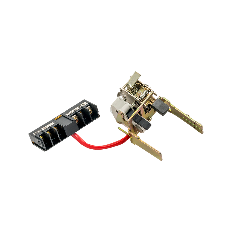 FT30 Series MCCB Shunt ReleaseThis shunt release is essential for remote tripping in molded case breakers. The product page indicates modular design and rated voltages, so it is worth checking if you need a dependable release for breaker assembly.View Product →
 KYM Series MCCB Arc Chute AssemblyThis arc chute assembly directly influences breaker interruption performance. The page notes a full production and testing setup, making it relevant for manufacturers aiming to pass timing tests consistently.View Product →
These are representative examples from the range Kaiyuanfeng supplies for 100 A to 800 A moulded case breakers and 1600 A to 4000 A frame breakers. The complete list of structural parts is available in the MCCB component assembly catalog.
Practical Checks for Buyers and Test Engineers
Engineers who evaluate breaker components, or who review timing certificates during commissioning, can reduce risk with a few checks. First, confirm what the certificate measured: release response, contact separation, or total clearing. Labels on different manufacturers' reports are not always identical. Second, compare the measured operating time with the live trip curve; if it drifts more than about 20-30% from the datasheet value, suspect worn springs, eroded contacts, or incorrect release settings. Third, when buying components for production, verify batch consistency in contact mass, spring rate, and alignment, because timing is a tolerance-sensitive performance.
- Ask for timing test data, not just a trip curve drawing, when qualifying a new supplier.
- Verify that internal accessory releases (shunt trip, undervoltage release) are tested at rated control voltage.
- During maintenance, measure opening time at the mechanism before and after contact replacement to track wear.
- Keep spare contact assemblies and arc chutes from the same production lot to preserve repeatable timing.
For anyone who wants a quick visual refresher on how the internal parts relate to the timing sequence, the guide to what is inside a molded case circuit breaker is a useful companion.
Frequently Asked Questions About Circuit Breaker Operating Time and Tripping Time
Q1: What is the difference between circuit breaker operating time and tripping time?
Tripping time is the interval from the start of the overcurrent until the release commands the mechanism to open. Operating time is the mechanical interval from that command until the contacts separate. Total clearing time adds arcing time.
Q2: What is a typical circuit breaker trip time at short circuit?
For low-voltage breakers, typical short-circuit trip times fall between 10 and 50 ms of total clearing. Release detection alone is often 2-20 ms, with mechanical opening and arcing adding the rest.
Q3: What is the opening time of a circuit breaker?
Opening time is the mechanical contact-separation time after the release energizes. Typical values are about 5-10 ms for MCBs, 10-25 ms for MCCBs, and 23-42 ms for medium- and high-voltage breakers in EPRI field data.
Q4: What does the trip curve on an MCCB datasheet mean?
The trip curve is a log-log plot of trip time versus current as a multiple of rated current. It shows the thermal overload region with inverse time and the instantaneous short-circuit region that is nearly flat, helping engineers verify protection coordination.
Q5: What factors affect circuit breaker tripping time?
Current magnitude, release type (thermal, magnetic, electronic), ambient temperature, mechanism friction, contact wear, and settings such as short-time delay all influence both tripping time and operating time.
Q6: How can I reduce circuit breaker trip time?
Use the instantaneous magnetic or electronic setting, keep the mechanism and contacts in good condition, and select releases with low mechanical inertia. Confirm that the change does not break discrimination with downstream breakers.
Previous Post
What Is Interrupting Rating of Circuit Breakers? Definition, Standards & Selection Guide
Next Post
Adjustable Circuit Breaker: What It Is and How to Choose the Right Tripping Setting
Related products
-
-
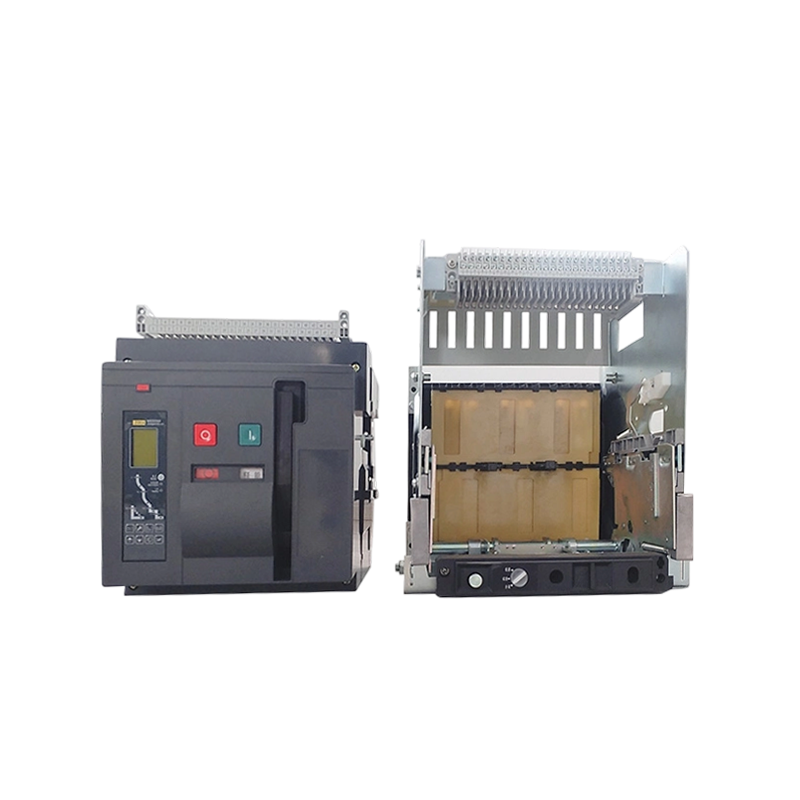
1.The circuit breaker provides safety protection, arc extinguishing, and interrupting functions, with defined electrical life and short-circuit withstand capability. 2.Multiple controller options are ...
See Details -
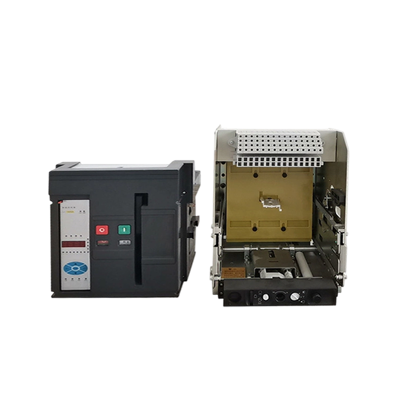
1. The circuit breaker offers safety protection, efficient arc extinguishing and interrupting, long electrical life, and short-term withstand capability. 2. The circuit breaker is available with a var...
See Details -
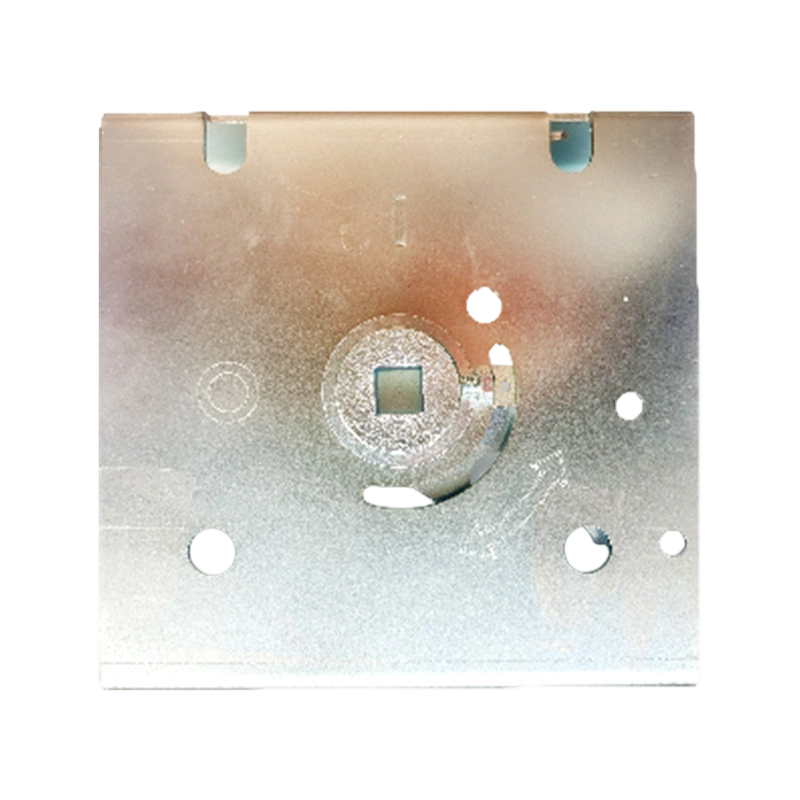
Featuring a simple structure with central operation and linkage-type transmission, this mechanism is compatible with three handle styles. It works with 63/100/250/400/630 frame molded case circuit bre...
See Details -

Featuring a simple structure, this mechanism is driven by an electric motor with a gear reducer, delivering high torque, fast switching, and reliable operation. It supports both AC and DC power, with ...
See Details -
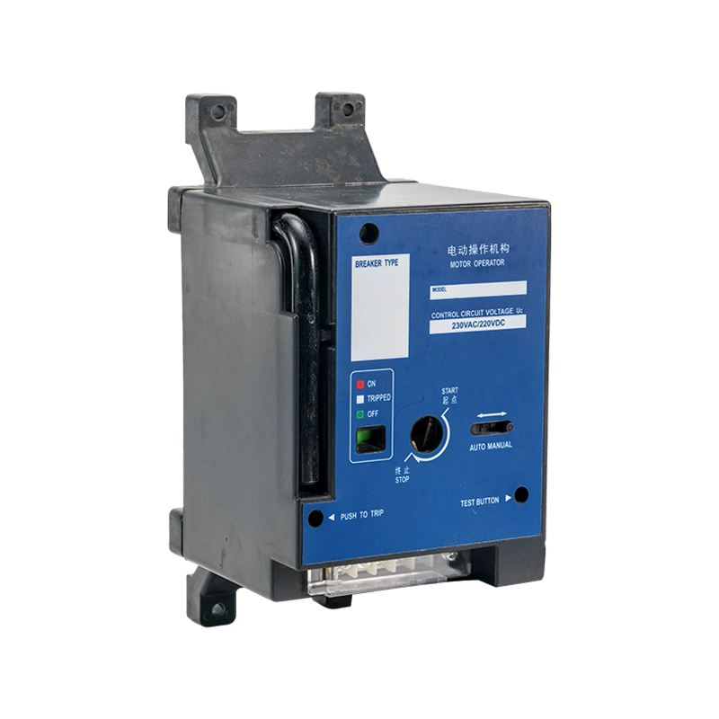
Featuring a simple structure, this mechanism is driven by an electric motor with a gear reducer, delivering high torque, fast switching, and reliable operation. It supports both AC and DC power, with ...
See Details

Copyright @ Kaiyuanfeng Electrical Machinery Manufacturing Co.,Ltd All Rights Reserved.
OEM MCCB Accessories Manufacturer
ISO Certified Circuit Breaker Factory
