 English
 中文简体
 русский
 عربى


1.The circuit breaker provides safety protection, arc extinguishing, and interrupting functions, with defined electrical life and short-circuit withstand capability. 2.Multiple controller options are ...
See Details
Circuit Breaker Connection: Terminals, Torque and Contact Interfaces Explained
Content
- 1 A Circuit Breaker Connection Is Three Interfaces, Not One
- 2 Bolt-On, Plug-In or Withdrawable: Matching the Interface to the Job
- 3 The Connection Inside the Case: Contact Pressure You Cannot Re-Torque
- 4 Conductor Preparation and Torque: Where Most Hot Joints Start
- 5 Busbar and Flexible Connections Above the 630 A Boundary
- 6 What to Check Before You Energise
- 7 Frequently Asked Questions
- 7.1 Q1. What is a circuit breaker connection?
- 7.2 Q2. What torque should I use on MCCB terminal bolts?
- 7.3 Q3. Can I connect an aluminium cable directly to a copper terminal?
- 7.4 Q4. Plug-in or withdrawable MCCB — which is better for maintenance?
- 7.5 Q5. How do I check contact resistance after reconnecting a breaker?
- 7.6 Q6. Why does my breaker trip immediately after reconnection?
There is a moment on every switchgear commissioning that decides whether the day ends on schedule: the torque wrench clicks on the last terminal bolt of a 630 A feeder breaker, and someone reaches for the micro-ohmmeter to compare the three phases. Almost every circuit breaker connection problem that surfaces months later — a terminal running far hotter than its neighbours, a nuisance trip at 80 % load, a discoloured lug — was decided long before that moment, in four choices: which interface was used, how the conductor was prepared, how tight the joint was made, and whether the contact system inside the case was still fit for the current.
The short version: a circuit breaker connection is a chain of three joints — the power terminal, the contact path inside the case, and the secondary control circuit — and it fails at the weakest link, not at the tightest bolt. Torque is necessary but never sufficient. The sections below explain how each link behaves, what to specify, and what to check before the panel is energised.
A Circuit Breaker Connection Is Three Interfaces, Not One
When an installer says "the connection", they usually mean the line and load terminals. That is only one of three interfaces, and on a molded case breaker all three sit within a few centimetres of each other.
- Power terminations. The line-side and load-side pads where cable lugs or busbars land. Current here runs from a few tens of amperes on a 63 A frame up to several thousand on a 6300 A air circuit breaker.
- The internal contact path. From the terminal, current travels through the case to the moving contact, the stationary contact and the flexible braids that carry current toward the mechanism. Contact force is set by springs and by the mechanism, and it is not adjustable in the field.
- Secondary and control circuits. Auxiliary and alarm contacts, shunt trips, undervoltage releases and motor operators. The currents are milliamps, but a loose or reversed control wire either prevents remote tripping or trips the breaker at the wrong moment.
Treat the three as separate acceptance criteria. A joint that passes a torque check can still be a bad connection if the internal contacts are worn, and a breaker with perfect contacts can still overheat because a lug was crimped with the wrong die.
Isometric view: the terminal pad, the contact system inside the sealed case and the secondary terminals are three different joints with three different failure modes.
Bolt-On, Plug-In or Withdrawable: Matching the Interface to the Job
The physical way a breaker connects to the busbar is normally decided at the design stage, and it fixes the maintenance procedure for the next twenty years. All three low-voltage options are still in wide use, and none of them is automatically better than the others.
| Interface | How the conductor lands | What maintenance looks like | Typical use |
|---|---|---|---|
| Bolt-on (fixed) | Cable lug or busbar bolted directly to the terminal pad | Breaker cannot be removed without isolating and unbolting the conductors | Feeders and final distribution where the load can be switched off |
| Plug-in | Breaker jaws pushed onto fixed busbar stubs; a plug-in device carries the moving half | Breaker swaps in minutes, but the panel must still be isolated first | Distribution boards with several identical outgoing ways |
| Withdrawable | Breaker mounted on a chassis that racks between connected, test and disconnected positions | Racking separates the main contacts; the busbar side stays live until the panel is isolated upstream | Incomers, bus couplers and critical feeders in switchgear |
The difference that catches people out is safety rather than convenience. Plug-in and withdrawable breakers both let you replace a device quickly, but only the withdrawable version gives a defined racked-out position with the main contacts separated inside the compartment.
Rated current ranges covered by the component series
Bar length is scaled to the largest rating shown (6400 A). Ranges are the series ratings published in the component catalogue for each platform.
 MZ2 Series MCCB Plug-in Device for 100–800 A FramesExternal accessory that lets compatible 100–800 A molded case breakers be replaced without disconnecting incoming or outgoing cables; conductive circuit uses T2 copper.View Product →
The Connection Inside the Case: Contact Pressure You Cannot Re-Torque
Everything downstream of the terminal is a connection no one can tighten again. The moving contact assembly — contact arm, tips, pressure spring, flexible braids and the welded joint between braid and arm — carries the full load current and every fault current the breaker interrupts. Contact pressure falls gradually as the mechanism wears, as arc products deposit on the tips and as braids fatigue. The terminal bolts stay exactly as they were left.
Two practical conclusions follow. First, a phase that runs hotter than its neighbours at the same load usually points inside the case rather than at the lug, so a thermal scan beats a torque re-check as a diagnostic. Second, parts like these are qualified items rather than commodity hardware: changing a braid cross-section or a weld process alters the thermal and short-circuit behaviour of the complete device, which is why manufacturers re-qualify the breaker rather than re-order whichever contact assembly is cheapest. A short walk through what sits inside a molded case circuit breaker shows the same components from the assembly side.
 KYM Series Molded Case Moving Contact Welding AssemblyOEM moving contact welding assembly for KYM-125 to KYM-800 MCCBs; manufacturer states compatibility with leading international breaker brands for manufacturing or repair supply.View Product →
Conductor Preparation and Torque: Where Most Hot Joints Start
Two joints cause most of the hot terminals found in the field, and both are made by hand: the crimped lug and the bolted terminal.
Start with the metal. Copper is forgiving; aluminium is not. Aluminium oxide re-forms within minutes of wire brushing, so the conductor has to be abraded, coated with a joint compound intended for the purpose, and separated from a copper terminal by a bimetallic transition plate or an aluminium-bodied lug. The compound excludes air and moisture — it is not a filler for a gap and it does not compensate for a loose bolt. Crimped lugs should be made with the die specified for that lug and cable size, and a sample cut open and inspected remains the cheapest quality check available on site.
Torque is the other half. Use the value printed in the instruction sheet of the breaker you are actually installing, not a generic table: terminal hardware, washer stacks, thread sizes and plating differ between platforms, and a figure that is correct for one frame can strip the threads of another. Two habits separate a joint that lasts from one that fails — a calibrated torque wrench instead of an impact driver or a feel-based judgement, and a paint line across the bolt head so the next person can see whether it has moved since commissioning.
Acceptance is finally measured in temperature rise, not in torque. IEC 61439-1 sets temperature-rise limits for the terminals and busbars of an assembly, and the usual field proof is a thermal scan taken with the panel under a meaningful load. A busbar joint that looks healthy at 10 % load tells you very little about how it behaves at 70 %.
Busbar and Flexible Connections Above the 630 A Boundary
Above roughly 400 A to 630 A, connection work stops being cable work and becomes busbar work: flat copper bars, often two to four per phase, bolted through with hardware that has to hold its preload through thousands of thermal cycles.
Three details decide whether that joint survives. Plating: tin-plated bar is normal for indoor switchgear, while silver or a heavier tin layer is used where the joint runs hotter or is expected to be disturbed during maintenance. Preparation: an oxidised or scratched contact face has to be cleaned and, in many workshops, re-plated, because oxide trapped under a bolted joint does not disappear when the bolt is tightened. Movement: rigid bars bolted between a breaker terminal and a fixed busbar transfer every expansion cycle into the terminal, so a flexible copper connector — laminated foils or a braided shunt — absorbs that movement and keeps the bolted joint stable.
Copper parts at this level are usually made to drawing rather than picked from a catalogue, so the tolerance of the bar, its hole pattern and its plating matter as much as the breaker itself. Buyers who need both catalogue breaker parts and drawing-based copper work usually want to know whether the supplier's business covers standard components and custom copper machining before they send the first enquiry.
 High-Purity Copper Bars for Conductive Connectors or Support ComponentsCopper bars made from a high-purity substrate and intended for processing into conductive connectors or support components; no further specifications are listed.View Product →
What to Check Before You Energise
A connection that passes these six checks rarely gives trouble in service. A connection that skips them usually announces itself at the worst possible load.
- Every power terminal torqued to the breaker manufacturer's published value, with the wrench within its calibration date.
- Conductors and lugs inspected for strand damage, correct stripping length and the correct crimping die.
- Phase-to-phase contact resistance compared with a micro-ohmmeter, with any outlier investigated before energising.
- Secondary wiring checked against the scheme drawing, then shunt trip, undervoltage release and auxiliary contacts proven by operating the breaker.
- Clearances and barriers verified, with no tools, washers or swarf left inside the compartment.
- Insulation resistance measured before energising, then a thermal scan taken at the first opportunity under real load.
Frequently Asked Questions
Q1. What is a circuit breaker connection?
It is three joints in series: the line and load terminals where cable or busbar is bolted, the contact system inside the sealed case, and the secondary control wiring. The connection performs only as well as its weakest joint.
Q2. What torque should I use on MCCB terminal bolts?
Whatever the breaker manufacturer's instruction sheet states for that model and terminal size. Under-torquing overheats the joint and over-torquing strips threads or stretches the bolt, so use a calibrated wrench and mark the bolt afterwards.
Q3. Can I connect an aluminium cable directly to a copper terminal?
Not bare metal to bare metal. Aluminium oxide re-forms within minutes and the aluminium-copper junction corrodes in damp air. Abrade and compound the aluminium, then separate the metals with a bimetallic transition plate or an aluminium-bodied lug.
Q4. Plug-in or withdrawable MCCB — which is better for maintenance?
Both allow a fast breaker swap. Only the withdrawable version has a defined racked-out position with the main contacts separated, which is why it dominates incomers and critical feeders. Plug-in units still require the panel to be isolated first.
Q5. How do I check contact resistance after reconnecting a breaker?
Inject DC through each phase with a micro-ohmmeter, compare the three readings with each other and with the value recorded at commissioning, and investigate any phase that reads noticeably higher before applying load.
Q6. Why does my breaker trip immediately after reconnection?
Usually a control-wiring problem rather than a power connection: a shunt trip or undervoltage release wired to the wrong side, auxiliary contacts set normally closed when the scheme needs normally open, or an undervoltage release held in without a supply. Check the secondary scheme first, then look for a short in the load.
Previous Post
Drawout Circuit Breaker Guide: Racking, Contact Systems and Component Choice
Next Post
Which Organizations Test and List Circuit Breakers? UL and Intertek Explained
Related products
-
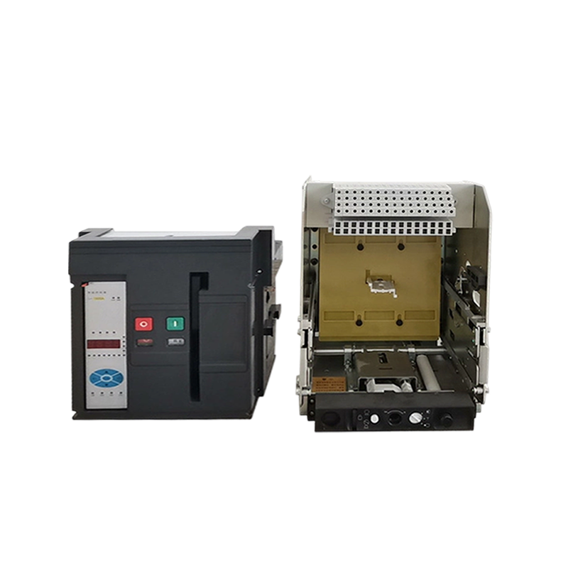
-
1.The circuit breaker provides safety protection, arc extinguishing, and interrupting functions, with defined electrical life and short-circuit withstand capability. 2.Multiple controller options are ...
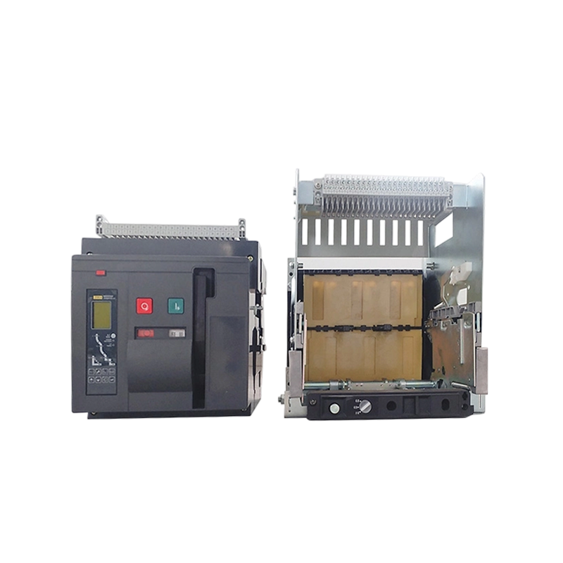
See Details -
1. The circuit breaker offers safety protection, efficient arc extinguishing and interrupting, long electrical life, and short-term withstand capability. 2. The circuit breaker is available with a var...
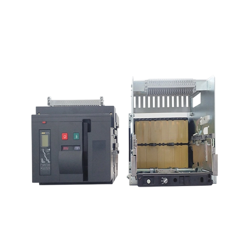
See Details -
Featuring a simple structure with central operation and linkage-type transmission, this mechanism is compatible with three handle styles. It works with 63/100/250/400/630 frame molded case circuit bre...
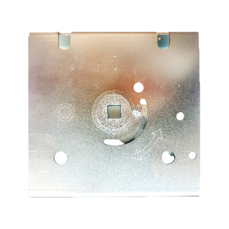
See Details -
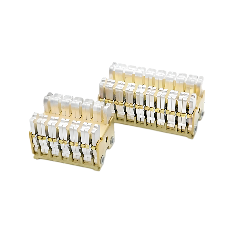
With tight contact and rapid on/off response, it is specially designed for ACB drawer bases.
See Details -
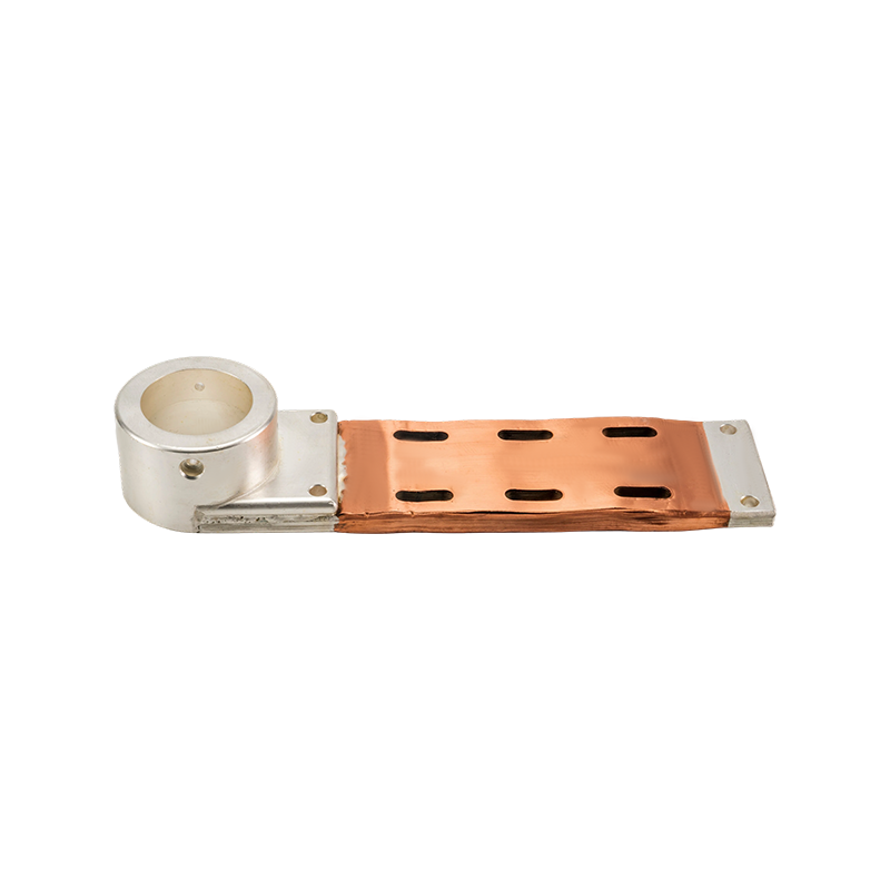
Provides consistent conductivity and flexibility, supporting current transmission in medium and low voltage equipment, with broad installation adaptability. Supports enhanced current carrying capacity...
See Details

Copyright @ Kaiyuanfeng Electrical Machinery Manufacturing Co.,Ltd All Rights Reserved.
OEM MCCB Accessories Manufacturer
ISO Certified Circuit Breaker Factory
