 English
 中文简体
 русский
 عربى


1.The circuit breaker provides safety protection, arc extinguishing, and interrupting functions, with defined electrical life and short-circuit withstand capability. 2.Multiple controller options are ...
See Details
On-Site Circuit Breaker Testing: Field Diagnostics That Find Component Faults
Content
- 1 What on-site testing can prove, and what it cannot
- 2 The field tests that matter most
- 3 Contact resistance: read the trend, not the number
- 4 Trip testing: the control circuit is part of the breaker
- 5 Auxiliary contacts and status circuits: the silent failure
- 6 A practical decision sequence for field results
- 7 Planning a test window without unnecessary downtime
- 8 What the results mean for component sourcing
- 9 Frequently asked questions
- 9.1 Q1. What is on-site circuit breaker testing?
- 9.2 Q2. How often should circuit breakers be tested?
- 9.3 Q3. What is contact resistance testing?
- 9.4 Q4. Can circuit breaker testing be done while the breaker is energized?
- 9.5 Q5. What causes a breaker to fail a trip test?
- 9.6 Q6. How do I decide between component repair and breaker replacement?
At 2 a.m., a plant electrician closes a 400 A MCCB, the breaker holds, and the line restarts. Three weeks later the same breaker refuses to trip during a fault, and the post-incident check finds a welded contact and a stiff trip lever. On-site circuit breaker testing is meant to find that gap while the breaker is still in service, not after the event.
The conclusion is simple: on-site testing works best as a condition check on the current path and the trip chain, not as a pass/fail ritual. One micro-ohm reading is noisy; a trend is not. A trip test that only asks “does it open” misses the timing drift that tells you the trip unit is aging. What follows is a practical field guide for maintenance teams and component buyers who need to act on the results.
What on-site testing can prove, and what it cannot
An on-site test cannot reproduce a full short-circuit laboratory test. It can, however, measure the breaker as installed: busbar and cable stress, ambient temperature, control voltage, mechanical alignment, and the condition of the current path after years of load cycling.
That difference matters. A lab result tells you whether the design meets a standard. A field result tells you whether this breaker, in this panel, still has enough contact material, enough spring pressure, and a trip chain that responds at the right time. Read the numbers as a comparison: phase against phase, current result against commissioning data, and measured trip time against the published curve.
The field tests that matter most
Most maintenance programs use a core set of measurements. The table below maps each test to the component that most often explains a poor result.
| Field test | What it measures | Common clue | Component usually implicated |
|---|---|---|---|
| Contact resistance | Resistance of the main current path | One pole more than 20% above the other two, or a rising trend | Moving contact, stationary contact, contact support, bolted joint |
| Insulation resistance | Phase-to-phase and phase-to-earth insulation | A sharp drop from baseline, or below 1 MΩ on a low-voltage breaker | Arc chute, insulated base, contaminated surface |
| Trip timing / trip profile | Time from current application to contact separation | Slow thermal trip, no instantaneous trip, inconsistent repeat tests | Trip unit, shunt trip, operating mechanism |
| Primary injection | The full current path at low voltage, including CTs and trip chain | Trips at the wrong multiple of the setting | Trip unit, current sensor, secondary wiring |
| Secondary injection | Protection relay and control circuit | Relay picks up but the breaker does not trip | Shunt trip, undervoltage release, auxiliary contact, wiring |
Contact resistance: read the trend, not the number
A micro-ohmmeter uses a four-wire Kelvin connection to push a known DC current through the closed contacts and measure the voltage drop. The result is reported in micro-ohms. The absolute value depends on frame size, contact material, and test-lead quality, so a single reading rarely justifies condemning a breaker.
What matters is the pattern. A phase-to-phase spread above roughly 20% is a common trigger for investigation. A 30–50% rise from the last test is more serious than a stable reading that happens to sit above a generic limit. Pitting, silver migration, contact misalignment, and loose busbar joints all show up as resistance drift before they show up as heat. For a closer look at the internal current path, see this guide to what is inside a molded-case circuit breaker.
In practice, the repair point is often the contact assembly, not the breaker terminals. The moving contact takes the arcing damage; the stationary contact takes the weld. If the contacts are pitted beyond cleaning, replacing the contact assembly is the controlled fix.
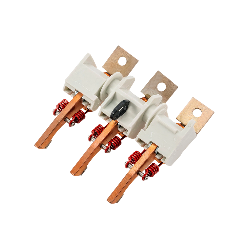 KYM Molded Case Moving Contact Assembly for MCCBsA complete OEM moving contact assembly for 125–800 MCCBs, relevant when pitted contacts need replacement rather than terminal repair.View Product →
Trip testing: the control circuit is part of the breaker
Trip timing tests apply current to the primary circuit and record when the contacts open. Secondary injection tests the protection relay and control circuit with a low-level signal. Both are useful, but they answer different questions. Primary injection proves the current path and trip unit work together. Secondary injection proves the control chain can command a trip.
A common field failure is a shunt trip that works on the bench but not in the panel. The cause is often control-voltage drop: a 24 Vdc coil that needs 70% of rated voltage to pick up may not operate at 18 Vdc after a long control-cable run. An on-site test with the actual control supply catches this; a bench test with a stable power supply does not.
 FT(S)-1600~6300 MCCB Shunt Trip UnitAn OEM shunt trip unit for 1600–6300 MCCBs, useful when verifying that actual control-supply voltage can command a trip.View Product →
Auxiliary contacts and status circuits: the silent failure
Auxiliary contacts do not carry the main current, so they are often left out of the test plan. That is a mistake. A stuck auxiliary contact can prevent a transfer scheme from confirming breaker position, or send a false “closed” signal to a PLC. The breaker may trip correctly and still leave the system in an unsafe state because the status circuit lied.
During on-site testing, exercise the auxiliary contacts through the full mechanical travel and check continuity at both ends. Look for silver migration across the contact gap, bent levers, and loose terminal screws. If the block is discolored or the lever has lost its spring return, replace the block rather than adjusting it.
 FC30 MCCB Auxiliary Contacts for 63–800 Frame SizesAuxiliary contact blocks for 63–800 frame MCCBs, useful for checking status circuits and replacing blocks with damaged levers or contacts.View Product →
A practical decision sequence for field results
- Verify the test setup before condemning the breaker. Check lead placement, battery level, and ambient temperature. A loose Kelvin clip can double a contact-resistance reading.
- Compare like with like. Use the same test current, lead length, and contact points as the previous test. Record the values in the breaker's maintenance file.
- Isolate the component. If one pole is high, swap leads and retest. If the reading follows the lead, the instrument is at fault. If it follows the pole, the contact path is at fault.
- Choose adjustment, component replacement, or breaker replacement. A loose joint can be re-torqued. A pitted contact can be replaced. A trip unit that fails repeatability after calibration is usually replaced.
- Re-test after the repair. A repair without a post-repair test is an assumption, not a verification.
Planning a test window without unnecessary downtime
On-site testing is a scheduling problem as much as a technical one. The safest sequence is to isolate the breaker, lock out the upstream device, and verify absence of voltage at the terminals. Primary injection and contact-resistance tests require the breaker to be de-energized; follow the test-set manufacturer's procedure and your site's arc-flash boundary.
- Confirm the breaker's published trip curve and the last test record before the window opens.
- Check control power at the panel, not at the battery bench; long control runs are a common cause of shunt-trip failures.
- Allow time for a second test after any adjustment or component swap.
- Have the likely replacement parts on site: contact assembly, auxiliary contact, shunt trip, and gasket set.
- Record ambient temperature and test-lead resistance; both affect micro-ohm readings.
What the results mean for component sourcing
A field test that points to a contact assembly, trip unit, or auxiliary block is a sourcing decision. For OEMs and maintenance teams, the goal is a component that matches the original mechanical interface and electrical rating, not a generic part that happens to fit the mounting hole. A mismatched contact assembly can change spring pressure, arc-runner alignment, and heat rise—three variables that on-site testing is supposed to control.
Kaiyuanfeng manufactures MCCB internal and external accessories, contact assemblies, arc chutes, trip units, and copper current-carrying parts for breaker builders and switchgear assemblers. Its catalogue is organized around the same breaker platforms and current ratings that field tests implicate. You can read more about the company's manufacturing focus on the about page, and match the replacement to the frame, current rating, and trip unit type before ordering.
Frequently asked questions
These are the questions maintenance and procurement teams ask most often when planning on-site circuit breaker testing.
Q1. What is on-site circuit breaker testing?
It is a set of field measurements—contact resistance, insulation resistance, trip timing, and injection tests—performed on an installed breaker to confirm it can clear a fault and isolate the circuit. It is not a full short-circuit laboratory test; it is a condition check on the current path and trip chain.
Q2. How often should circuit breakers be tested?
Most low-voltage maintenance programs test annually or at the start of a major outage cycle. Critical breakers in continuous process plants may be tested more often. The interval should follow duty cycle, fault history, and the last test trend, not a single calendar rule.
Q3. What is contact resistance testing?
A micro-ohmmeter passes a known DC current through the closed contacts and measures the voltage drop. The result indicates the condition of the contact interface and bolted joints. A rising trend or a phase-to-phase spread above about 20% is a reason to investigate.
Q4. Can circuit breaker testing be done while the breaker is energized?
Some tests, such as thermal imaging and secondary injection with the primary isolated, can be done with the breaker in service or partially isolated. Contact resistance and primary injection require the breaker to be de-energized and locked out. Follow the site's arc-flash and lockout/tagout procedures.
Q5. What causes a breaker to fail a trip test?
Common causes include a drifting trip unit, a marginal shunt trip coil, a stiff mechanism, or a control circuit with voltage drop. The test result usually points to one of these; it rarely means the entire breaker is beyond repair.
Q6. How do I decide between component repair and breaker replacement?
If contact resistance can be restored by replacing a contact assembly, or the trip chain can be restored by replacing a shunt trip or auxiliary block, component repair is usually the lower-risk path. Breaker replacement makes sense when the arc chute, mechanism, and trip unit all show wear, or when the frame is obsolete.
Previous Post
No previous article
Next Post
Drawout Circuit Breaker Guide: Racking, Contact Systems and Component Choice
Related products
-
-
1.The circuit breaker provides safety protection, arc extinguishing, and interrupting functions, with defined electrical life and short-circuit withstand capability. 2.Multiple controller options are ...
See Details -
1. The circuit breaker offers safety protection, efficient arc extinguishing and interrupting, long electrical life, and short-term withstand capability. 2. The circuit breaker is available with a var...
See Details -

We are equipped with: A full range of welding machines Various riveting equipment Multiple assembly lines Complete testing equipment These assemblies are compatible with products from leading internat...
See Details -
Used as a disconnector switch in ring main units, ensuring reliable switching.
See Details -

1.Housing rating: 500A 2.Tripping mechanism compatible with molded case circuit breakers 3.Feedback signal output compatible with molded case circuit breakers 4.Independent contact structure design, e...
See Details

Copyright @ Kaiyuanfeng Electrical Machinery Manufacturing Co.,Ltd All Rights Reserved.
OEM MCCB Accessories Manufacturer
ISO Certified Circuit Breaker Factory
